In an industrial setting, there can be a multitude of potential issues, and the correct installation and wiring methods are crucial for ensuring safety in production. Through today’s case study, we will explore together how to ensure safety in industrial production.
1. Description of the Problem
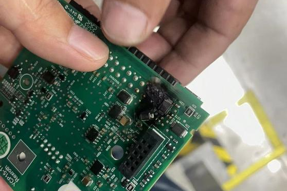
A terminal customer was using the 485 communication module CT-5321 for communication with a frequency inverter. They encountered a situation where six communication cards in the frequency inverter burned out successively. After replacing the inverter cards six times (each time resulting in burnout), the CT-5321 communication module itself burned out on the sixth occasion.
To prevent further customer losses, ODOT engineers visited the site to assist in troubleshooting.
2. On-site Troubleshooting
After careful observation and analysis by the engineers on-site, the following issues were identified:
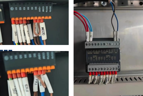
(1)There are 14 control cabinets on-site, each containing two frequency inverters and one energy meter that need to communicate with CT5321.
(2)The GND of the frequency inverter is connected to the shielding layer of the signal line.
(3) Upon examining the wiring of the frequency inverter, it was found that the communication ground and the inverter ground were not separated.
(4)The shielded wire of the RS485 signal line is not connected to the ground.
(5)The RS485 communication terminal resistors are not connected.
3. Cause Analysis
Based on the observations and analysis of the on-site situation, the engineer provided the following insights:
(1)The damaged components and modules did not exhibit signs of damage typical of electrostatic discharge (ESD) or surge. Unlike ESD or surge damage, which usually does not result in burnt components, the burnt components in CT-5321 were related to the RS485 port’s electrostatic protection device. This device typically has a DC breakdown voltage of around 12V. Therefore, it was deduced that the voltage on the RS485 bus had exceeded 12V, possibly due to the introduction of a 24V power supply.
(2)The RS-485 bus had multiple high-power devices and energy meters. In the absence of proper isolation and grounding, these devices could create a significant potential difference. When this potential difference and energy are substantial, it is possible to form a loop on the RS485 signal line, leading to the destruction of devices along this loop.
4. Solution
In response to these on-site issues, ODOT engineers proposed the following solutions:
(1)Disconnect the signal shielding layer from the inverter GND and connect it separately to the signal ground.
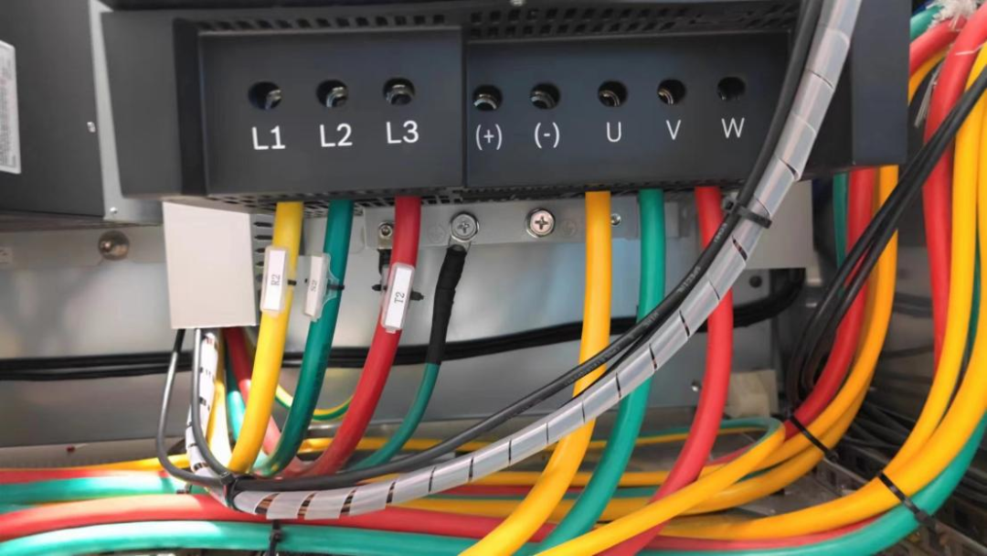
(2) Ground the inverter equipment, separate the signal ground, and ensure proper grounding.
(3) Add terminal resistors for RS485 communication.
(4)Install RS-485 isolation barriers on devices on the RS-485 bus.
5. Rectification diagram
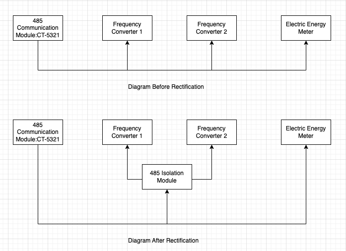
The implementation of the above rectification measures can effectively prevent similar problems from occurring again, ensuring the interests and safety of the customers.
At the same time, ODOT also reminds customers to pay attention to similar issues in the design and maintenance of communication systems, strengthen equipment maintenance and management, and ensure the stability and reliability of the system.
Post time: Feb-01-2024


